
Cart is empty

Bottom PCB: ISP Header 01 W*L(mm): Pitch(mm):
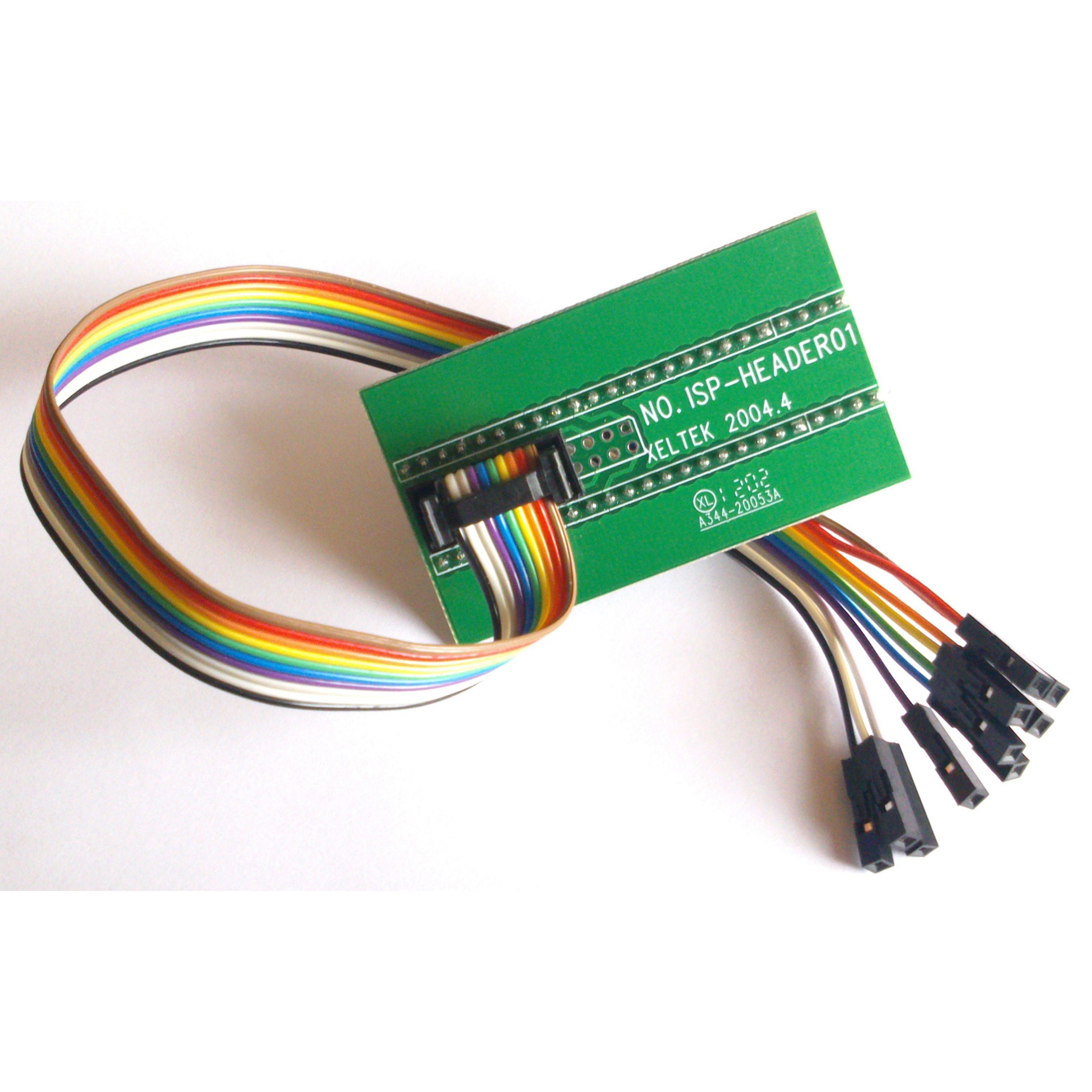
How do I use my ISP Xeltek Adapter, ISP-HEADER01?
The PCB end of the header is placed bottom justified on the ZIP socket of the programmer. See Fig. A.5.1.

Fig. A.5.1.
ISP cables could be used with selected parallel programmers to perform serial programming.
Select your in-circuit progarammable chip on our software. If ISP mode of programming is supported under your programmer, an ISP mark will be indicated in front of your chip part number on our software. Select this device name on our software. An adapter information dialog box will appear indicating what pins will be used on your chip and what color signal line, from the ISP-HEADER01, it's associated with. For example, see Fig. A.5.2 for the adapter information dialog box for MICROCHIP (ISP)PIC10F200.

Figure A.5.2
ISP Header-01 Adapter Pinout Information
The PCB end of the adapter is composed of 48 pins, dual in line layout. Only the last 5 pins of each column of pins is used. So, it is just a 10 pin header.
Here is the pin mapping layout:
Pin#1 --> Brown
Pin#2 --> Orange
Pin#3 --> Green
Pin#4 --> Purple
Pin#5 --> White
Pin#6 --> Black
Pin#7 --> Grey
Pin#8 --> Blue
Pin#9 --> Yellow
Pin#10 -->Red


